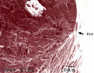
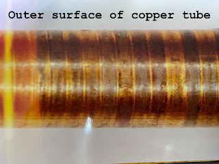
Figure 1: CFC initiated from surface pit
Corrosion fatigue cracks generally propagated from the pits or discontinuities initiated by chemical reaction or mechanical action [4,5]. In case of chemical reaction, especially for 300 series stainless steels, pits normally result from the corrosive action of chloride [6,7].
In case of mechanical action, discontinuities resulted from the abrasion between meshes which caused the metal loss via extensive plastic deformation, as indicated by deformation twins. Under cyclic load, pits and discontinuities become the stress concentration sites [8] which are the initiation sites for corrosion fatigue cracks. In addition, residual stress introduced from cold drawing as seen by the high density of twin grains could contribute to the failure by increasing the susceptibility of wire to pitting and cracking.
CFC is in certain aspects similar to stress corrosion cracking (SCC) [9]. As a result, fractography is required to distinguish between CFC and SCC. The failure by CFC can be confirmed by macroscopic beach marks, which indicate the propagation of cracks due to fatigue, and microscopic striation pattern, which indicates the crack propagation distance in each loading cycle. However, in austenitic stainless steels, striation pattern can hardly be identified [10] even at high magnification. Therefore, striation pattern cannot be identified in this work. Moreover, CFC can be confirmed by the characteristics of cracks which must have blunt crack tips, unbranched and consist mostly of transgranular cracks [11].
Figure 2: Single crack and blunt tip
References
[1] B.D. Craig. Material Failure Modes, Part I: A Brief Tutorial on Fracture, Ductile Failure, Elastic Deformation, Creep, and Fatigue, JFAP 2005; 5(5): 13-14, 39-45.
[2] S. Roychowdhury et al., Effect of pH and specimen orientation on the corrosion fatigue behavior of a duplex stainless steel in chloride solutions, Trans. Indian Inst. Met. 2004; 57(3): 265-70.
[3] C.R. Gagg and P.R. Lewis, In-service fatigue failure of engineered products and structures – Case study review, Eng Fail Anal 2009; 16(6): 1775-93.
[4] R. Ebara, Corrosion fatigue phenomena learned from failure analysis, Eng Fail Anal 2006; 13: 516–25.
[5] C.R. Gagg and P.R. Lewis, Failure of components and products by engineered-in defects – case studies, Eng Fail Anal 2005; 12(6): 1000–26.
[6] M. G. Fontana, Corrosion Engineering, third ed., New York, McGraw-Hill, 1967: 51-4.
[7] S.A.M. Refaey, Corrosion and Inhibition of 316L stainless steel in neutral medium by 2-Mercaptobenzimidazole, Int. J. Electrochem. Sci. 2006; 1: 80-91.
[8] M. Cerit, K. Genel, S. Eksi, Numerical investigation on stress concentration of corrosion pit, Eng Fail Anal 2009; 16(7): 2467–72.
[9] T. Magnin, Recent advances for corrosion fatigue mechanisms, ISIJ Int 1995; 35(3): 223-33.
[10] N.W. Sachs, Understanding the Surface Features of Fatigue Fracture: How They Describe the Failure Cause and the Failure History, JFAPBC 2005: 11-5.
[11] Denny A. Jones, Environmental Induced Cracking, Principles and Prevention of Corrosion, second ed., Prentice Hall International Inc., 1996 : 244-8
[12] N.J. Laycock and R.C. Newman, Temperature dependence of pitting potentials for austenitic stainless steels above their critical pitting temperature, Corrosion Science 1998; 40(6):887-902.


ขอบคุณสำหรับบทความดีๆที่ช่วยให้ผมเข้าใจได้มากขึ้น
ตอบลบขอบคุณครับพี่สยาม