วันอังคารที่ 29 มิถุนายน พ.ศ. 2553

Failure of Boiler Tube in Heat Recovery Steam Generator (HRSG) System by Flow-accelerated Corrosion

I would like to show my case study of failure analysis of boiler tube. It failed by FAC .

Introduction


Flow-accelerated corrosion (FAC) is metal loss through the dissolution of the protective oxide film by localized turbulence in water or wet steam piping system [1]. The metal corrosion is accelerated by the continuous erosive destruction of the protective layers. Under certain water chemistry, fluid velocity, and operating conditions, FAC can cause internal wall thinning of condensate and feed-water piping, heater drip and drain lines, and other carbon steel piping [2]. In some cases, this thinning has led to catastrophic failures and fatalities.

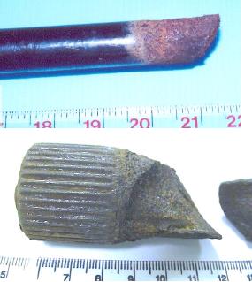
Fig.1 Boiler tube for failure analysis


In this case study, the failed component was the evaporator tube, which had been in service for nearly 4 years. The tube was the component of the evaporator outlet of the low-pressure steam in the heat recovery steam generator (HSRG). The tube was used for feeding water to the continuous process for boiler. During operation, it was exposed to hot water (120-200 C) and the pressure of 4-6 Bar (depends on the flow rate). The water solution has pH around 8.4-9.4, conductivity 3.8-7.5 micro-S/cm, silica content 4-20 microgram/l and iron content 3-24 microgram/l. The fluid flow velocity was about 0.3 M/s (flow rate 0.217 kg/s). The liquid ammonia was added into the water to control the pH value, and the hydrazine was also added to reduce oxygen content. The outer part of the tube was exposed to exhaust gas from the gas turbine (520 C and atmospheric pressure). The tube material was made of carbon steel grade ASTM SA-178A, which was 1.5 inches diameter and 0.094 inch thick. One section of the tube was replaced with a new ASTM SA106B steel tube by welding.


Fig.2 Longitudinal cross cut showing metal loss patterns

Fig.3 Horse shoe patterns, indicative of FAC was found on the inner tube surface

The bended surface of the tube revealed the damage from an erosion-corrosion type mechanism which is known as flow-accelerated corrosion (FAC). The attack was caused by a combination of flow velocity (mechanical factors) and corrosion (electrochemical factors). Especially at the site where a continuity surface was uneven such as weld bead at the inner wall of the tube during welding process, the erosion corrosion was extremely severe. Also the metal on the surface was removed and became particles. The most significant effect of erosion corrosion is the constant removal of protective films from the metal surface, thus resulting in localized attack at the area at which the film is removed [3]. This phenomenon is usually caused by movement at high velocities, and will be particularly prone to occur by the solution containing solid particle (e.g. silica, iron, insoluble salts, sand and silt) that has an abrasive action. Affected tube surface will often contain horseshoe pattern, grooves, or wavelike marks that indicate the attack direction. From the internal inspection of evaporator tubes using SEM, it revealed that the tube had an internal weld bead. This defect can be a potential source of small particles when these sites are attacked by erosion corrosion. In addition, hydrazine, a reducing agent, was added to the feed-water system in petrochemical plant to maintain a reducing environment in the steam generators. Hydrazine is reactive and unstable. It reacts with oxygen forming water and nitrogen. Un-reacted hydrazine would thermally decompose to form ammonia. FAC rate increases with increasing hydrazine level as the oxidizing–reducing potential becomes more reducing. The service temperature around 120-200 C is susceptible to FAC [1]. High flow rates, turbulence, and flow impingement increase water-steel contact and thereby increase the rate of iron dissolution and corrosion. FAC is most severe at abrupt flow discontinuities. Corrosion rate is higher at turbulence promoters such as irregular welds or changes in pipe diameter that is consistent with our results. In the area of FAC, the interaction between flow and the electrochemical processes of corrosion produces a characteristic abrasion pattern. The surface appearance ranges from smooth to pitted, but a distinctive wave-like appearance or horseshoe pattern with smooth scallops and sharp crests is found on the severe site as confirmed by microstructural analysis. The metal particles in the working fluid combine with silica also cause wear damage.

Fig.4 Macrostructure showing the wave patterns


Suggestions

Most cases of erosion corrosion can be minimized by

1. Redesigning or replacing the bended section with a larger radius tube.
2. Controlling the weld bead inside the tube during and after welding process.

3. Operating under homogenization of the water temperature and flow rate.

4. Maintaining the cleanliness of the fluid.

5. Selecting the material with high erosion corrosion resistant

6. Choosing the same grade and diameter of the pipe to be joint together

7. Avoiding overfeed of hydrazine and control the feed rate to match the water rate.

References:
[1] R.B. Dooley, V.K. Chexal, 2000, “Flow-accelerated corrosion of pressure vessels in fossil plant”, International Journal of Pressure Vessels and Piping, Vol.77, pp.85-90.
[2] Crispin Hales, Kelly J. Stevens, Philip L. Daniel, Mehrooz Zamanzadeh, Albert D. Owens., 2002, “Boiler feedwater pipe failure by flow-assisted chelant corrosion”, Engineering Failure Analysis, Vol.9, pp.235-243.
[3] R.D. Port, 1998, “Flow Accelerated Corrosion”, Nace International, paper no.721.

วันจันทร์ที่ 28 มิถุนายน พ.ศ. 2553

จะป้องกันรถของท่านไม่ให้เกิดการกัดกร่อนได้อย่างไร (How to prevent your car from corrosion)

“การกัดกร่อนสามารถสร้างความเสียหายให้กับรถของคุณได้ ลองใช้วิธีดังกล่าวเพื่อป้องกันไม่ให้รถของคุณเกิดการกัดกร่อน”

รูปที่ 1 รถในสภาพที่เจ้าของดูแลดี (รถผมเองครับ อิอิ)

สำหรับรถยนต์นั้น บางท่านอาจถือว่าเป็นแค่เครื่องอำนวยความสะดวกสำหรับการเดินทางเท่านั้น แต่อาจเป็นทุกสิ่งทุกอย่างสำหรับบางท่าน (เป็นทั้งบ้าน ที่นอนและอื่นๆ) แต่เจ้าของรถทั้งหลายเหล่านี้ไม่สามารถอยู่นิ่งได้ถ้าพบรอยขีดข่วนบนรถตัวเอง และจะเจ็บปวดมากถ้าพบว่ารถของตัวเองเกิดสนิม ดังนั้นวิธีที่จะป้องกันไม่ให้เกิดการกัดกร่อน (สนิม) คือการดูแลเอาใจใส่อย่างดี


รูปที่ 2 รถยนต์ที่เกิดการกัดกร่อนบนผิวเหล็กที่อยู่ภายใต้สีเคลือบที่หลุดร่อน

เป็นที่ทราบกันดีว่า สาเหตุสำคัญของการกัดกร่อนในรถยนต์ ก็คือ เกิดการสะสมของสิ่งสกปรก ความชื้นหรือสารเคมี (แต่ถ้าในต่างประเทศก็อาจจะมาจากการสะสมของเกลือที่ใช้ในการละลายหิมะบนท้องถนน) โดยเฉพาะในบริเวณที่เข้าถึงหรือกำจัดได้ยาก (ซอกหรือหลืบทั้งหลาย) เช่นบริเวณใต้ท้องรถ กรอบประตู รอยบิ่น รอยขีดข่วนหรือความเสียหายใดๆ ที่เกิดบนผิวสีอันเกิดจากอุบัติเหตุเล็กน้อยหรือรอยถลอกที่เกิดจากการกระแทกของหินและกรวด จุดบกพร่องเหล่านี้แหละครับ จะเป็นกักเก็บสะสมของสารที่มีฤทธิ์กัดกร่อน (Corrosive Media)

รูปที่ 3 บริเวณใต้ท้องรถมักเป็นที่สะสมของดินและโคลน


รูปที่ 4 ท่อลำเลียงน้ำมันเกิดการกัดกร่อนจนรั่วเนื่องจากใช้งานในแถบบางขุนเทียนซึ่งมีไอเกลือสูง
(จากรูปที่ 4 จากลักษณะที่ปรากฏดังกล่าวแสดงให้เห็นว่าผิวหน้าชิ้นงานด้านที่สัมผัสบรรยากาศภายนอกสามารถสัมผัสกับบรรยากาศที่มีองค์ประกอบของสารที่มีฤทธิ์กัดกร่อน จนทำให้ผิวหน้าของเหล็กชิ้นส่วนรถยนต์ถูกทำลายนำไปสู่การกัดกร่อน ซึ่งเป็นบริเวณที่ง่ายต่อการกัดกร่อนและเป็นจุดเริ่มต้นการแตกร้าว และเกิดผลิตภัณฑ์การกัดกร่อน (corrosion products) เป็นสนิมสีน้ำตาล-แดง และสารที่มีฤทธิ์กัดกร่อนซึ่งปะปนอยู่กับสิ่งแวดล้อม เช่น ปะปนกับดินโคลน เป็นต้น รูปแบบการกัดกร่อนแบบนี้เกิดขึ้นทั่วผิวหน้าของโลหะ ทำให้โลหะเกิดการสูญเสียเนื้อโลหะ ทำให้ชิ้นงานบางลงและเกิดรูรั่วบริเวณที่บางที่สุด)

สภาวะสิ่งแวดล้อม เช่น ฝุ่นสารเคมี บรรยากาศใกล้ชายฝั่งทะเล หรือมลพิษจากอุตสาหกรรมมักเป็นปัจจัยเร่งให้เกิดการกัดกร่อน โดยเฉพาะในสภาวะที่มีความชื้นสูงเหนือจุดเยือกแข็งมักเป็นสภาวะที่เลวร้ายที่สุดสำหรับรถยนต์ กล่าวคือ อัตราการกัดกร่อนจะเร็วมากในสภาวะดังกล่าว

ดังนั้น วิธีการที่ดีที่สุดในการรักษาผิวหน้ารถของคุณและช่วยหลีกเลี่ยงการกัดกร่อน คือ การทำความสะอาดโดยการล้างรถอยู่เป็นประจำ (นอกจากนี้ การล้างรถเป็นประจำในช่วงฤดูหนาวและทันทีหลังฤดูหนาวยังช่วยป้องกันการกัดกร่อนในรถยนต์ได้สำหรับประเทศที่มีหิมะ) และที่สำคัญก็คือรักษาสภาพภายใต้ท้องรถให้สะอาดและแห้งที่สุดเท่าที่จะทำได้ จากประสบการณ์ในการวิเคราะห์ความเสียหายของชิ้นส่วนยานยนต์ของผม พบว่าเกือบทุกส่วนประกอบของรถยนต์มีโอกาสเกิดการกัดกร่อนได้ทั้งนั้น ไม่ว่าจะเป็น Radiator ชิ้นส่วนชุบโครเมียมเพื่อความสวยงาม ชิ้นส่วน torsion bar แตร หม้อน้ำ ล้อแม็ก หรือแม้แต่แบตเตอรี่

สำหรับสีเคลือบรถยนต์แล้ว ถ้ามีสิ่งแปลกปลอม เช่น เกลือ ทาร์ มูลนก และเศษจากอุตสาหกรรมที่ร่วงหล่นมาเกาะติดและถ้าทิ้งไว้อาจทำลายผิวหน้าสีเคลือบรถยนต์ได้ ดังนั้นควรกำจัดสารตกค้างให้เร็วที่สุด แต่ถ้ากำจัดออกยากควรเลือกใช้สารทำความสะอาดที่เหมาะสม โดยสารเหล่านั้นต้องไม่ทำลายผิวหน้าสีเคลือบของรถยนต์

ควรซ่อมรถและให้เสร็จทันทีในบริเวณที่เกิดการเสียหายของรถโดยเฉพาะบริเวณที่เกิดรอยขีดข่วนหรือเกิดการหลุดออกของสีเพื่อป้องกันการกัดกร่อนที่จะเกิดขึ้นกับเหล็ก

ความชื้น สิ่งสกปรกหรือโคลนสามารถสะสมตามพื้นและสามารถทำให้เกิดการกัดกร่อนได้ ดังนั้นจึงควรตรวจสอบบริเวณดังกล่าวอยู่เป็นประจำ เพื่อให้แน่ใจว่ามีความสะอาดและแห้ง และจะต้องตรวจสอบบ่อยยิ่งขึ้นถ้าคุณนำรถไปวิ่งนอกถนน เข้าป่าเข้าดง (Off-road) หรือวิ่งในฤดูฝน ควรทำความสะอาดรถของคุณด้วยสารละลายที่มีส่วนผสมของสบู่หรือสารทำความสะอาดที่มีฤทธิ์อ่อนๆ ผสมกับน้ำอุ่น เพื่อกำจัดสิ่งสกปรกที่ติดตัวรถเพื่อป้องกันการกัดกร่อน

รูปที่ 5 รถยนต์ประเภท OFF-Road ถ้าทำความสะอาดไม่ดีก็เกิดการกัดกร่อนได้ง่าย

สถานที่จอดรถยนต์เป็นปัจจัยที่สำคัญอีกประการหนึ่งที่ช่วยป้องกันการกัดกร่อน เราจะต้องมั่นใจว่ารถไม่ได้จอดในบริเวณที่มีความชื้นหรือบริเวณที่มีการถ่ายเทอากาศไม่ดี เนื่องจากถ้าโรงเก็บรถมีความชื้นสูงจะเร่งการกัดกร่อนได้เร็วยิ่งขึ้น ถ้าคุณไม่สามารถจอดรถในโรงเก็บรถได้ ก็แนะนำให้หาอุปกรณ์มาปกคลุม การปกคลุมด้วยวัสดุที่มีคุณภาพนอกจากจะช่วยป้องกันรังสียูวี ซึ่งมักทำลายสีของรถ ชิ้นส่วนที่เป็นพลาสติกและผ้าให้ซีดจางลงแล้ว ยังช่วยป้องกันการเกาะติดของฝุ่นและมลพิษทางอากาศบนพื้นผิวของรถท่านได้

รูปที่ 6 ล้อแม็กที่มักเกิดการกัดกร่อนแบบใต้ชั้นเคลือบ (Filiform Corrosion)

รูปที่ 7 การกัดกร่อนที่เกิดขึ้นกับแบตเตอรี่

รูปที่ 8 การกัดกร่อนที่เกิดขึ้นกับชิ้นส่วน torsion bar ซึ่งมีดินโคลนเกาะติด โดยเจ้าของรถไม่ทำการชะล้างออกจนเกิดการกัดกร่อนและเป็นจุดเริ่มต้นการแตกหักในที่สุด

รูปที่ 9 การกัดกร่อนที่เกิดขึ้นกับชิ้นส่วนประตูเนื่องจากการเตรียมผิวไม่ดีก่อนการเคลือบ เมื่อนำไปใช้งานจึงเกิดการบวมของสีรถ ถ้าอย่ในช่วงประกันก็สามารถเคลมได้

ปล. หลืบ = crevice site แปลว่าซอก ที่อับอากาศ

เพื่อให้เข้าใจเพิ่มขึ้น โปรดศึกษาเพิ่มเติมได้จาก
http://siamkaewkumsai.blogspot.com/2010/05/galvanic-corrosion.html
ซึ่งจะกล่าวถึงความแตกต่างระหว่างการเคลือบด้วยสารที่เสถียรกว่าและด้อยกว่าบางส่วน

Hydrogen embrittlement of steel

Fig.1 : The bolt used in many contructions

Hydrogen embrittlement is a form of environmentally assisted failure which is caused by the action of hydrogen often in combination with residual or applied stress resulting in the reduction of the load bearing capacity of a component [1]. The cause of the embrittlement is the penetration of atomic hydrogen into the structure of metal. Generally a small quantity of hydrogen is sufficient to cause failures because it has the ability to magnify its effect by migrating to regions of high tri-axial stress. Hydrogen embrittlement manifests itself in diverse modes of material failures each of which is highly specific to the alloy system. In all cases, the fracture of bolt takes place starting from the root of the last engaged thread [2]. Hydrogen can be formed on the material surface both during a manufacturing process and during service. During manufacturing the most common sources of hydrogen is in acid cleaning and electrolytic plating. In the service life, hydrogen can be generated by the dissolution of hydrocarbon gases and cathodic protection system [3].

Fig.2 : Macrofractography of the failed bolt

The fractography revealed the concave fracture surface, typical indicates that there was a serious stress concentration [4]. The stress concentration played an important part in causing the failure, such as a sharp corner on a step in a shaft.

Fig.3 : Microfractography showing the intergranular in the case hardend layer

The material did not exhibit much plasticity during fracture, which was anticipated from an embrittlement type of failure [5]. The presence of intergranular hairline cracks indications along grain facets on the fracture surface point to hydrogen embrittlement.

The presence of a ductile fracture mode at the core and an intergranular fracture mode at the outer surface of a case hardening bolt is typical of hydrogen embrittlement [6], but could also be stress corrosion cracking (SCC). However, SCC can be eliminated, because the microstructure analysis results showed no presence of branched cracks.

Many hydrogen embrittlement mechanisms have been proposed, but none is universally accept. However, the phenomenon of hydrogen embrittlement is widely present. Evidences found in this case can be explained in a supportive manner through several mechanisms as mono-atomic hydrogen as small interstitial atom diffuse very rapidly above room temperature, eventually accumulates at voids/defects and other metallurgical discontinuities. With increase in concentration of hydrogen at such discontinuities, a high internal pressure is produced that enhances void growth and results in separate of grains. The hydrogen diffusion took place under the influence of residual stress, introduced in the material during thermal quenching treatment. The presence of hydrogen in steel reduces the strength of materials. It can be cause premature failure under static load. The time for failure depends on the stress applied to the component and the amount of hydrogen that has diffused in to steel. Because of this characteristic, hydrogen embrittlement is sometimes called hydrogen induced crack failure.

The probable causes for entrapment of hydrogen in this material were heat treatment of the steel under uncontrolled furnace atmosphere and subsequent of quenching process. Similar failure of cadmium plated 4140 steel [7] accumulator ring for aerospace application due to hydrogen embrittlement, on account of insufficient stress relieving after cadmium plating has been reported else where.

References

[1] R.K. Dayal and et al., “Hydrogen embrittlement in power plant steels”, Sadhana, Vol. 28, Parts 3&4, 2003, pp. 431–451.
[2] Milan M.T., “Failure analysis of a SAE 4340 steel locking bolt”, Eng Fail Anal, Vol. 11, 2004, pp. 915–924.
[3] Karl P. Fischer, “Bolter og Bolteforbindelser offshore”, MATERIALDAGEN 2003, 2003.
[4] Sachs N.W., “Understanding the Surface Features of Fatigue Fractures: How They Describe the Failure Cause and the Failure History”, JFAP, Vol.5, 2005, pp.11-15.
[5] Victor K., “Failed Main Rotor Pitch Horn Bolt from an Army Attack Helicopter”, Handbook of Case Histories in Failure Analysis, ASM, Vol. 2, pp.338-391, 1996.
[6] Mark Tanner, G., Hydrogen Embrittlement Failure of Socket Head Cap Screws, “Handbook of Case Histories in Failure Analysis”, ASM, Vol.1, pp.332-334, 1996.
[7] A.K. Jha et al., “Hydrogen embrittlement of 3.5Ni–1.5Cr–0.5Mo steel fastener”, Eng Fail Anal, Vol. 15, 2008, pp. 431–439.

วันอาทิตย์ที่ 27 มิถุนายน พ.ศ. 2553

Corrosion Fatigue Cracking of Austenitic Stainless Steel

Today, I would like to present the corrosion fatigue cracking, the mode of failure that found in the austenitic stainless steel. The details are as following;

Figure 1: CFC initiated from surface pit

Corrosion fatigue cracking (CFC) is the failure mode normally found in various metals and alloys under cyclic load in various environments [1]. Although austenitic stainless steel is resistant to uniform corrosion, it is sensitive to localized corrosion. It is widely known that austenitic stainless steel components are susceptible to pitting corrosion when exposed to chloride containing environment. In case of service under cyclic load, pitting corrosion is normally followed by subsequent corrosion fatigue cracking [2,3].

Corrosion fatigue cracks generally propagated from the pits or discontinuities initiated by chemical reaction or mechanical action [4,5]. In case of chemical reaction, especially for 300 series stainless steels, pits normally result from the corrosive action of chloride [6,7].

In case of mechanical action, discontinuities resulted from the abrasion between meshes which caused the metal loss via extensive plastic deformation, as indicated by deformation twins. Under cyclic load, pits and discontinuities become the stress concentration sites [8] which are the initiation sites for corrosion fatigue cracks. In addition, residual stress introduced from cold drawing as seen by the high density of twin grains could contribute to the failure by increasing the susceptibility of wire to pitting and cracking.

CFC is in certain aspects similar to stress corrosion cracking (SCC) [9]. As a result, fractography is required to distinguish between CFC and SCC. The failure by CFC can be confirmed by macroscopic beach marks, which indicate the propagation of cracks due to fatigue, and microscopic striation pattern, which indicates the crack propagation distance in each loading cycle. However, in austenitic stainless steels, striation pattern can hardly be identified [10] even at high magnification. Therefore, striation pattern cannot be identified in this work. Moreover, CFC can be confirmed by the characteristics of cracks which must have blunt crack tips, unbranched and consist mostly of transgranular cracks [11].


Figure 2: Single crack and blunt tip

In addition to corrosive species and loading condition, temperature is also another factor influencing the failure of engineering components, especially stainless steel components. As the temperature increases, the pitting potential decreases, causing the component to be more susceptible to pitting corrosion in chloride solution [12]. Once pitting occurs, it becomes an initiation site for CFC.

References
[1] B.D. Craig. Material Failure Modes, Part I: A Brief Tutorial on Fracture, Ductile Failure, Elastic Deformation, Creep, and Fatigue, JFAP 2005; 5(5): 13-14, 39-45.

[2] S. Roychowdhury et al., Effect of pH and specimen orientation on the corrosion fatigue behavior of a duplex stainless steel in chloride solutions, Trans. Indian Inst. Met. 2004; 57(3): 265-70.

[3] C.R. Gagg and P.R. Lewis, In-service fatigue failure of engineered products and structures – Case study review, Eng Fail Anal 2009; 16(6): 1775-93.

[4] R. Ebara, Corrosion fatigue phenomena learned from failure analysis, Eng Fail Anal 2006; 13: 516–25.

[5] C.R. Gagg and P.R. Lewis, Failure of components and products by engineered-in defects – case studies, Eng Fail Anal 2005; 12(6): 1000–26.

[6] M. G. Fontana, Corrosion Engineering, third ed., New York, McGraw-Hill, 1967: 51-4.

[7] S.A.M. Refaey, Corrosion and Inhibition of 316L stainless steel in neutral medium by 2-Mercaptobenzimidazole, Int. J. Electrochem. Sci. 2006; 1: 80-91.

[8] M. Cerit, K. Genel, S. Eksi, Numerical investigation on stress concentration of corrosion pit, Eng Fail Anal 2009; 16(7): 2467–72.

[9] T. Magnin, Recent advances for corrosion fatigue mechanisms, ISIJ Int 1995; 35(3): 223-33.

[10] N.W. Sachs, Understanding the Surface Features of Fatigue Fracture: How They Describe the Failure Cause and the Failure History, JFAPBC 2005: 11-5.

[11] Denny A. Jones, Environmental Induced Cracking, Principles and Prevention of Corrosion, second ed., Prentice Hall International Inc., 1996 : 244-8

[12] N.J. Laycock and R.C. Newman, Temperature dependence of pitting potentials for austenitic stainless steels above their critical pitting temperature, Corrosion Science 1998; 40(6):887-902.

วันศุกร์ที่ 25 มิถุนายน พ.ศ. 2553

รูปแบบการเสียหายของวัสดุ : การล้า (Fatigue)

วันนี้เราเรียนรู้รูปแบบการเสียหายของวัสดุในรูปแบบถัดมา นั่นก็คือ การล้า หรือ Fatigue จะมีรายละเอียดเป็นอย่างไร เชิญติดตามได้เลยครับ

คำว่า "fatigue" มาจากคำภาษาละติน "fatigare" แปลว่า "เหนื่อย" ซึ่งหมายความว่าวัสดุเสียหายเร็วกว่าที่คาดไว้หลังจากเกิดการล้าภายใต้การรับแรงแบบคาบหรือรอบ (Cyclic Loading) ความล้าเป็นเกณฑ์ที่สำคัญที่สุดในการออกแบบวัสดุทางวิศวกรรม ความรุนแรงของความเสียหายจากการล้าคือบ่อยครั้งเกิดขึ้นที่ความเค้นต่ำกว่าค่า yielding of materials อายุการใช้งานของความล้าขึ้นอยู่กับจำนวนรอบที่วัสดุสามารถทนได้ก่อนเกิดการแตกหัก การแตกหักอาจเกิดขึ้นได้ภายในไม่กี่รอบ หรือบางครั้งอาจใช้เวลานานหลายรอบจึงจะเกิดการแตกหักได้

รูปที่ 1 ผิวหน้าแตกหักจากการล้าของเพลาเหล็กกล้าไร้สนิม

การล้า เป็นรูปแบบการเสียหายที่เกิดขึ้นกับวัสดุมากที่สุด และน่าสนใจเป็นพิเศษ เนื่องจากเป็นรูปแบบการเสียหายที่มีแรงเค้นมากระทำกับวัสดุในค่าที่ต่ำกว่าค่าที่ออกแบบไว้มาก โดยจากข้อมูลที่มีการสำรวจ พบว่าการเสียหายด้วยด้วยรูปแบบดังกล่าวคิดเป็นประมาณ 90% ของการแตกหักของวัสดุทั้งหมด 

การล้า (Fatigue) หมายถึง การที่ชิ้นงานรับแรงซ้ำไปซ้ำมาหรือเป็นคาบ (Cyclic Load) เช่น ดัดไป-ดัดมาดึงปล่อย-ดึงปล่อย หมุนไป-หมุนมา บิดไป-บิดมา หรือแรงดันเพิ่ม-ลดลงไปมา เป็นต้น ส่งผลให้เกิดรอยร้าวขึ้น รอยร้าวที่เกิดจะมีขนาดใหญ่ขึ้นเรื่อยๆ ภายในชิ้นงาน จนในที่สุดชิ้นงานจะเหลือพื้นที่ในการรับแรงเพียงเล็กน้อย และเกิดการแตกหักทันทีทันใดเมื่อได้รับความเค้นเพียงเล็กน้อย แรงที่ว่านี้เมื่อนำมาคำนวณต่อพื้นที่ (Stress) จะพบว่ามีค่าต่ำกว่าค่าความเค้นที่ใช้ในการออกแบบ เช่น ค่าความเค้นที่จุดคราก (Yield Stress) ความเสียหายเนื่องจากการล้าถือว่าเป็นการเสียหายแบบเปราะมักไม่ปรากฏลักษณะที่เตือนล่วงหน้าเหมือนการแตกหักแบบเหนียวที่มีการยืดตัวให้เห็นจึงเป็นอันตรายมาก ตัวอย่างชิ้นส่วนเหล็กกล้าไร้สนิมที่เสียหายจากการล้าแสดงในรูปที่ 1 และ Liberty Ship ที่เสียหายด้วยกลไกการล้าแสดงดังรูปที่ 2

รูปที่ 2 Liberty Ship เสียหายด้วยกลไกการล้า

การเสียหายเนื่องจากการล้าเกิดขึ้นเมื่อวัสดุเกิดการแตกหักออกเป็นสองชิ้นหรือมากกว่า หลังจากรับแรงเค้นแบบคาบ (Cyclic Stress) เป็นระยะเวลาที่ยาวนานต่อเนื่องกัน ค่าความเค้นสูงสุดสำหรับการเสียหายเนื่องจากการล้าจะต่ำกว่าค่าความต้านทานแรงดึงสูงสุด (Ultimate Tensile Strength) ของวัสดุ ถ้าสามารถควบคุมแรงเค้นที่กระทำให้มีค่าต่ำ และอยู่ในระดับที่คงที่ การเสียหายด้วยรูปแบบดังกล่าวจะเกิดขึ้นได้ยากมาก แรงกระทำที่เป็นคาบทำให้เกิดจุดเริ่มและการขยายตัวของรอยแตก และถ้าวัสดุเกิดการแตกร้าวจนไม่สามารถที่จะรองรับแรงได้อีกก็เกิดการแตกหักในที่สุด


กลไกการเสียหายจากการล้าแบ่งได้เป็น 3 ขั้นตอน (ดังรูปที่ 3) คือ

1. การเริ่มต้นของรอยแตก (Crack Initiation)

2. การขยายตัวของรอยแตก (Crack Propagation) และ

3. การแตกหักของวัสดุ (Material Rupture)


รูปที่ 3 แสดงตำแหน่งการขยายตัวของรอยแตกจากการล้าภายความเค้นตามแนวแกนทั้ง 3 ขั้นตอน


ลักษณะที่เกิดขึ้นคล้ายกับการแตกหักแบบเหนียวและการแตกหักแบบเปราะ คือ รอยแตกจากการล้า จะเริ่มบริเวณที่เป็นจุดบกพร่องของวัสดุ ได้แก่ ร่อง หลุม ความไม่ต่อเนื่องของผิวหน้า รอยบิ่น และจุดบกพร่องอื่นๆ จุดบกพร่องที่เกิดขึ้นบนผิวหน้าวัสดุดังกล่าวจะแสดงตัวเป็นจุดรวมความเค้น เมื่อเกิดการสะสมของแรงเค้นจนเกินขีดจำกัดของค่าความแข็งแรง ณ จุดนั้นของวัสดุ และเกิดเป็นรอยร้าวตามมา วิธีที่ดีเพื่อป้องกันการเสียหายจากการล้าตัวคือ ต้องกำจัดจุดที่แสดงตัวเป็นจุดรวมความเค้น คือพยายามกำจัดหรือลดจุดบกพร่องบนผิวหน้าวัสดุ และลดค่าความกว้างของแรงเค้น (Stress Amplitude) รอยแตกจากการล้าจะขยายตัวไปตามบริเวณที่เป็นจุดอ่อนในวัสดุ ดังนั้นการลดจำนวนจุดบกพร่องภายในเนื้อวัสดุ เช่น ช่องว่างและสารเจือปนจะเพิ่มระยะเวลาการขยายตัวของรอยแตก เมื่อรอยแตกที่เกิดขึ้นทำให้วัสดุไม่สามารถรองรับแรงที่กระทำต่อไปได้ จึงเกิดการแตกหัก ซึ่งสามารถเกิดขึ้นได้ทั้งจากแรงเฉือนและแรงดึง

แม้ว่าการล้าจะเป็น time dependent process แต่การล้าไม่ได้ขึ้นอยู่กับเวลามากนักแต่จะขึ้นอยู่กับจำนวนรอบของแรงที่กระทำมากกว่า โดยรอบ (Cycle) ประกอบด้วยแรงเค้นที่กระทำจะเพิ่มขึ้นจากจุดเริ่มต้น (ในบางกรณีมีค่าเป็นศูนย์หรือติดลบ) จนถึงค่าสูงสุดที่เป็นบวก และลดลงผ่านค่าเริ่มต้นจนถึงค่าต่ำสุด (ในบางกรณีจะเป็นค่าของแรงกระทำที่มีค่าติดลบมากที่สุด) และสุดท้ายก็จะกลับมายังค่าเริ่มต้น (รูปที่ 4) อย่างไรก็ตาม แรงกระทำที่มีค่าเป็นลบจะไม่ใช่ค่าเป็นจุดเริ่มของการล้า แต่จะเกิดขึ้นกับค่าแรงเค้นมีค่าเป็นบวก มากไปกว่านั้นความเค้นแบบคาบไม่จำเป็นต้องมีลักษณะที่สมมาตร แต่สามารถเกิดขึ้นได้แบบสุ่ม โดยทั่วไปโลหะกลุ่มเหล็ก หรือโลหะเหล็กผสม เป็นวัสดุที่มีขีดจำกัดความทนทาน (Endurance Limit; SL) ค่านี้จะบอกว่าเมื่อวัสดุได้รับความเค้นน้อยกว่าความเค้นนี้ จะไม่เกิดความเสียหาย ไม่ว่าจะรับความเค้นไปกี่รอบก็ตาม แต่ถ้าเป็นโลหะนอกกลุ่มเหล็ก (Non-ferrous Metals)  เช่น อะลูมิเนียม และไทเทเนียม จะไม่มีค่าขีดจำกัดความทนทาน โลหะจะเสียหายเมื่อการรับแรงแบบคาบมีค่าเกินจำนวนรอบที่เหมาะสมกับวัสดุนั้นๆ (ต้องมีการทดลองหาจำนวนรอบที่ทนได้เมื่อกำหนดค่าความเค้นให้) ในขณะเดียวกัน การเพิ่มค่าความเค้นสูงสุด (Stress Amplitude) สามารถทำให้เกิดการเสียหายด้วยการล้าที่จำนวนรอบต่ำๆ ส่วนโลหะนอกกลุ่มเหล็กดังแสดงในรูปที่ 5 นอกจากนี้ยังเป็นการชี้ว่าเมื่อวัสดุได้รับภาระและมีความเค้นเปลี่ยนแปลงเป็นรอบกลับไป-กลับมาหรือซำ้ไป-ซ้ำมา วัสดุจะมีขีดจำกัดที่จะรับความเค้นได้น้อยลง

ปล.ตามทฤษฎีแล้ว Endurance Limit หรือ ขีดจำกัดความทนทาน 


รูปที่ 4 Fatigue loading cycle


รูปที่ 5 S-N Curves ของโลหะกลุ่มเหล็กและนอกกลุ่มเหล็ก

โลหะและโพลิเมอร์จะมีความไวต่อการเสียหายจากการล้าตัว ในขณะที่เซรามิกส์มีความต้านทานที่ดี 

ปัจจัยที่ช่วยลดความเสี่ยงต่อการเสียหายแบบล้า ได้แก่ การเลือกวัสดุ ความเข้มข้นของความเค้น ผิวสำเร็จ และความต่อเนื่องของวัสดุ
  • การเลือกใช้วัสดุ มีความสำคัญยิ่งต่อการพิจารณาการออกแบบทั้งหมด การเลือกวัสดุอาจถูกจำกัดด้วยปัจจัยหลายประการ รวมถึงข้อจำกัดด้านเศรษฐกิจ สิ่งแวดล้อม และข้อจำกัดในการใช้งาน การเลือกวัสดุที่มีขีดจำกัดความทนทานสูง (Endurance Limit) เป็นวิธีปฏิบัติที่ดี
  • ความเข้มข้นของความเค้น โดยพื้นฐานแล้ว มุมที่แหลมทั้งหมดควรทำเป็นรัศมีถ้าเป็นไปได้ มุมแหลมจะให้ความเข้มข้นของความเค้นและมักเป็นสาเหตุของรอยแตกเริ่มต้น
  • การตกแต่งพื้นผิว เป็นองค์ประกอบที่สำคัญอีกประการหนึ่ง จากที่เรียนมาเราจะพบว่าในการกำหนดค่าการแรงหลายๆ แบบ เช่น การดัดและการบิด ความเค้นวิกฤตมักจะอยู่ที่พื้นผิว ดังนั้นโดยทั่วไปแล้วพื้นผิวที่ปราศจากตำหนิจะเพิ่มความต้านต่อการล้าได้ดี
  • ความไม่ต่อเนื่องของวัสดุ เป็นสิ่งที่หลีกเลี่ยงไม่ได้ในระดับจุลภาค แต่กระบวนการขึ้นรูปที่ดีจะช่วยลดปัญหาเหล่านี้ได้
การเสียหายด้วยรูปแบบการล้ามีหลายชนิด ได้แก่ การล้าที่รอบสูง การล้าที่รอบต่ำ การล้าเนื่องจากความร้อน การล้าที่ผิว การล้าเนื่องจากการกระแทก การล้าร่วมกับการกัดกร่อน และการล้าเนื่องจากการถูครูด รายละเอียดจะเป็นอย่างไร โปรดติดตามตอนต่อไปโดยคลิคที่ด้านล่าง
http://siamkaewkumsai.blogspot.com/2010/07/fatigue.html
สำหรับการวิเคราะห์ผิวหน้าแตกหักจากการล้าสามารถดูได้จากลิงค์ด้านล่าง
http://siamkaewkumsai.blogspot.com/2010/05/fatigue-fracture.html

Ten Mechanical Failure Modes

วันนี้จะมานำเสนอรูปแบบการเสียหายทางกลพื้นฐาน 10 รูปแบบในฉบับภาษาอังกฤษ แต่ผมจะทยอยลงรายละเอียดที่เป็นภาษาไทยในหัวข้อรูปแบบการเสียหายวัสดุ ซุ่งก็ได้ลงรายละเอียดไปบ้างแล้ว

มีการกล่าวขานกันว่าแรงที่กระทำกับระบบของเราสามารถนำไปสู่ความเสียหายได้หลายรูปแบบ
(Forces imposed on systems can cause failures in many different ways)


Engineers have to take system and environmental forces into account when designing a system or a component , whether the system is a microchip or a skyscraper.


How Understanding Mechanical Failure Modes Improves the Design Process

Components can fail in a variety of different ways based on geometry, load direction, environmental conditions, or other variables. By understanding how something could fail, engineers can design the component to minimize the probability of failure. Designers generally use a factor of safety when designing critical parts. A factor of safety is a multiplier added to design criteria to ensure that not only does the part perform properly under normal loadings, but also performs properly under occasional overloadings

The ten primary modes for failure of mechanical components include:


Buckling - Buckling is the failure of a long, slender column that has been subjected to a compressive, axial load. As the load is applied, the center of the column span bulges outward, and then either cracks or yields, depending on the material properties of the specific component.

Corrosion - Corrosion is the chemical alteration (generally, but not always, oxidation), of a material due to environmental exposure to corrosive elements. For example, iron or steel that is exposed to air can undergo oxidation, forming iron oxide, commonly known as rust. This reddish-brown material has virtually no structural strength, and can reduce the effective material cross section, and therefore strength of a structure.

Creep - Creep is the slow deformation of a solid material over time due to applied loads and often increased temperatures. Creep can result in changes in material properties and part geometries that can cause failures.

Fatigue - Fatigue is a reduction in the ultimate strength of a material due to cyclic loading of a part. Micro-deformations can occur in loads that are larger than the normal working load. Even elastic deformations can result in material changes that can reduce the ultimate strength over a large number of cycles.

Fracture - Fracture begins as a localized microcrack in a part that slowly grows over time, or grows rapidly when exposed to a large overload. Failure occurs when the crack growth becomes critical and the part breaks. Crack growth often begins in areas of high stress concentration, such as corners.

Impact - Impact failure, just as it sounds, is the failure of a part due to impact with or by another object. A baseball shattering a window is an impact failure.

Rupture - Rupture generally occurs in pressure vessels or other containers when the pressure within the vessel exceeds the strength of a vessel, either globally or locally. Overpressure can cause rupture, as well as localized reduction in wall thickness due to corrosion or wear.

Thermal Shock - Thermal shock is the result of a component moving quickly from one temperature extreme to another. For example, brittle materials such as cast iron experience thermal shock if a hot part is suddenly cooled. The part can then crack or shatter because the material does not have the ductility to withstand the sudden thermal contraction of the material.

Wear - Wear is the gradual removal of material by two parts rubbing against each other, or environmental contact with a part, such as water or sand. As material is removed, the effective cross section of a load bearing part is reduced, increasing the stress on the part even though the applied load is constant.

Yielding - Yielding is the stress failure of a part due to overloading. As a load is applied to the component, the stress in the part increases. Based on the stress-strain curve for that particular material, the yield point is essentially the peak load that the part can hold before the material stretches apart.

While every operating environment contains different variables, engineers need to understand the different modes of failure so that they can design their parts with a factor of safety large enough to minimize the probability of failure during normal working operations and during potential overloading conditions.

รายละเอียดเพิ่มเติมสามารถอ่านได้ที่ http://mechanical-engineering.suite101.com/article.cfm/ten_mechanical_failure_modes

วันพฤหัสบดีที่ 24 มิถุนายน พ.ศ. 2553

Determination of Trace Metals in Lubricating Oils

น้ำมันหล่อที่ไม่ดี (มีสารปลอมปน) สามารถนำสู่การสึกหรอของชิ้นส่วนได้ โดยเฉพาะส่วนประกอบของเครื่องยนต์และกังหัน เป็นต้น ดังนั้นเราจะตรวจสอบหาโลหะแปลกปลอมในน้ำมันหล่อลื่นได้อย่างไร

เขียนโดย Prof Ricardo Aucelio (Pontificia Universidade Catolica do Rio de Janeiro)
อ่านเพิ่มเติมได้ที่ http://www.scitopics.com/Determination_of_Trace_Metals_in_Lubricating_Oils.html

Engine and turbine components undergo continual wear under normal operating conditions; this is minimized by the use of lubricating oils. Lubricating oils from petroleum are mainly composed of paraffinic, naphthenic and, to a lesser extent, aromatic hydrocarbons. Several additives, including metallo-organic ones, are also part of the final composition of commercial lubricating oil. Wear has both physical (friction between metallic parts, high temperature and pressure) and chemical (corrosion) sources. Chemical wear may produce not only metallic particles but also soluble metallo-organic species, whereas physical wear generates metallic particles of varying sizes (up to a few micrometers). Part of the metallic debris is not retained by filters and collectors, remaining in the lubricating oil and being transported through the whole system. Increasing amounts of some key elements in the lubricating oil may indicate the extent of the wear of wetted components. For instance, an abrupt increase of Ni, Sn or Cr indicates corrosion in bearings, valves and pistons, Fe indicates corrosion in various parts, Na indicates oil contamination with anti-freeze fluids and so on. The diagnosis based on elemental analysis of used lubricating oils may indicate the need for preventive maintenance of engines and turbines before irreversible damage occurs. Besides bringing economic benefits, such diagnoses save lives. The Spectroscopy Oil Analysis Program (SOAP) of the United States Air Force was the pioneer program based on this type of monitoring.Elements such as Ag, B, Ba, Bi, Ca, Cd, Co, Cr, Fe, Hg, Mg, Mo, Ni, P, Sb, Se, Sn, Ti and Zn, are also deliberately introduced in small portions to lubricating oils to address requisites for special applications. In these cases, metallo-organic compounds containing these elements act as additives, improving lubricating capability and properties such as antioxidant, anticorrosive, dispersing, antiwear, and others. The improvement of performance of the oil is dependent upon the amount of the additive introduced; therefore, these amounts must be strictly controlled. Sensitive techniques are required for analysis of used lubricating oils since the capability of monitoring small concentration changes in the key elements is needed. The complexity of the oil matrix, its viscosity and the high organic load impose serious difficulties for elemental analysis. Such determinations are also an analytical challenge because all wear metals (solid particles of different sizes and metallo-organic species) must be accurately determined for information purposes. Apart from the existence of a few electroanalytical and XRF methods for the determination of Zn, Cu, Pb, Fe, Cr, Ni, As and Cd in lubricating oils, the majority of analytical methods reported in the literature are based on atomic spectrometric techniques such as FAAS, ET AAS, DC or ICP OES, ICP MS and AFS (From Aucélio R.Q. et al. (2007, The Determination of trace metals in lubricating oils by atomic spectrometry. Spectrochim. Acta ., 62: 952-961).

Engine and turbine components undergo continual wear under normal operating conditions; this is minimized by the use of lubricating oils. Lubricating oils from petroleum are mainly composed of paraffinic, naphthenic and, to a lesser extent, aromatic hydrocarbons. Several additives, including metallo-organic ones, are also part of the final composition of commercial lubricating oil. Wear has both physical (friction between metallic parts, high temperature and pressure) and chemical (corrosion) sources. Chemical wear may produce not only metallic particles but also soluble metallo-organic species, whereas physical wear generates metallic particles of varying sizes (up to a few micrometers). Part of the metallic debris is not retained by filters and collectors, remaining in the lubricating oil and being transported through the whole system. Increasing amounts of some key elements in the lubricating oil may indicate the extent of the wear of wetted components. For instance, an abrupt increase of Ni, Sn or Cr indicates corrosion in bearings, valves and pistons, Fe indicates corrosion in various parts, Na indicates oil contamination with anti-freeze fluids and so on. The diagnosis based on elemental analysis of used lubricating oils may indicate the need for preventive maintenance of engines and turbines before irreversible damage occurs. Besides bringing economic benefits, such diagnoses save lives. The Spectroscopy Oil Analysis Program (SOAP) of the United States Air Force was the pioneer program based on this type of monitoring.Elements such as Ag, B, Ba, Bi, Ca, Cd, Co, Cr, Fe, Hg, Mg, Mo, Ni, P, Sb, Se, Sn, Ti and Zn, are also deliberately introduced in small portions to lubricating oils to address requisites for special applications. In these cases, metallo-organic compounds containing these elements act as additives, improving lubricating capability and properties such as antioxidant, anticorrosive, dispersing, antiwear, and others. The improvement of performance of the oil is dependent upon the amount of the additive introduced; therefore, these amounts must be strictly controlled. Sensitive techniques are required for analysis of used lubricating oils since the capability of monitoring small concentration changes in the key elements is needed. The complexity of the oil matrix, its viscosity and the high organic load impose serious difficulties for elemental analysis. Such determinations are also an analytical challenge because all wear metals (solid particles of different sizes and metallo-organic species) must be accurately determined for information purposes. Apart from the existence of a few electroanalytical and XRF methods for the determination of Zn, Cu, Pb, Fe, Cr, Ni, As and Cd in lubricating oils, the majority of analytical methods reported in the literature are based on atomic spectrometric techniques such as FAAS, ET AAS, DC or ICP OES, ICP MS and AFS (From Aucélio R.Q. et al. (2007, The Determination of trace metals in lubricating oils by atomic spectrometry. Spectrochim. Acta ., 62: 952-961).

Further reading

Aucélio R.Q. et al. (2007). The Determination of trace metals in lubricating oils by atomic spectrometry. Spectrochim. Acta ., 62: 952-961.

Varnes A.W. (1985). Analytical methods for the analysis of petroleum products, Spectrosc. 1: 28-33.

Sychra V. et a.. (1981) Analysis of petroleum and petroleum products by atomic absorption

K.J. Eisentraut (1984) Spectrometric oil analysis. Detecting engine failures before they occur, Anal. Chem. 56: 1086A-1091A.

Vahaoja P. et al. (2005) Determination of Wear Metals in Lubrication Oils: A Comarison Study of ICP-OES and FAAS, Anal. Sci. 21: 1365-1369.

พาทินาของทองแดง: วิวัฒนาการของชั้นผลิตภัณฑ์การกัดกร่อนในบรรยากาศ องค์ประกอบทางเคมี ผลของสภาพแวดล้อม และความสำคัญต่อการอนุรักษ์วัสดุ

  บทคัดย่อ ทองแดงและโลหะผสมทองแดงเป็นวัสดุที่มีความสำคัญทั้งในงานวิศวกรรม สถาปัตยกรรม และศิลปกรรม เนื่องจากมีสมบัติเชิงกลที่เหมาะสม สามารถขึ...