S. Kaewkumsai, S. Aumparn, and E. Viyanit
National Metal and Material Technology
Center (MTEC),
National Science and Technology
Development Agency (NSTDA),
114 Thailand Science Park, Paholyothin
Rd., Klong 1,
Klong Luang, Pathumthani 12120 THAILAND
Phone 66-2564-6500 ext. 4736, Fax.66-2564-6332,
E-Mail: siamk@mtec.or.th
ABSTRACT
This paper described the failure of stainless steel
shaft grade AISI 316, which has been investigated after being in service for
nearly 3 years. It failed by stress corrosion cracking, which was originated at
the welded zone. The investigation included visual examination, optical
microscopy, scanning electron microscopy (SEM), energy dispersive spectroscopy
(EDS), spectrometry, and metallography. Analytical results revealed that crack
was propagated at the outer surface of the welded zone. Significant evidence of
pitting was observed in the originated zones which results from the corrosion
attacked. It is necessary to check the material properties after welding
process and one should ensure that the residual tensile stresses is prohibited.
KEY WORDS:
Stress Corrosion Cracking; Stainless Steel;
Branched Crack
1. Introduction
Stress corrosion cracking (SCC) is a term used to
describe failures in engineering parts that result from environmentally
assisted cracks propagation. This phenomenon is associated with a combination
of stresses above some threshold values, specific environment and sensitive
material, which leads to surface cracks especially in passive film forming
metal [1]. Austenitic stainless steel parts were frequently subject to failure
from stress corrosion cracking in chloride containing environments. To induce
SCC, a high chloride concentration is required, although relatively small
amount of chloride is sufficient on heated surfaces, area where chloride
concentration can occur, or where chloride is concentrated by pitting or
crevice corrosion. The cracking continues at low stresses and commonly occurs
as a result of residual stresses from welding or manufacturing. The cracking is
normally transgranular, although it may switch to intergranular mode as a
result of sensitization of the steel.
In service, welding residual stresses can superpose on
applied stress and if being tensile in nature, they may promote SCC. For
on-site application, the maximum residual stresses produced in the welding
process may be higher than the yield strength of material [2]. Since the
breakdown of passive films has been recognized as playing a key role in the
pitting and SCC of austenitic stainless steels, it is reasonable to correlate
the effects of microstructure and residual stress on corrosion resistance to
the properties of the passive film.
The failed material for failure analysis was the
stainless steel screener shaft, which had been in service for nearly 3 years.
The shaft was made of commercial stainless steel grade AISI 316. The shaft was
used for vibrated the screener of plastic powder. The vibration amplitude and
frequency cycles were controlled around 3 mm and 1000 cycle/second,
respectively. The temperature in serviced was exposing around 80-90 ºC. The
shaft was fabricated by welding process without preheat and post-heat at the
welded location and fracture was found in this area. The fractured shaft for
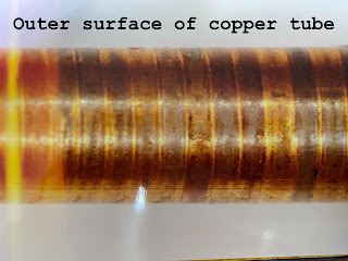
failure analysis is shown in Fig.1.

Fig.1 As- received screener
shaft for failure analysis and fracture site
2. Investigation Methods and Results
2.1 Visual Examination
As-received fractured shaft was thoroughly examined
visually with the aid of a stereo microscope. The shaft had fractured into two
pieces. A portion of one of the mating fracture surfaces was cut away from the
shaft and used for fractography. The fracture surface, which cut from as
received failed shaft, was carefully examined both visually and the aid of a
stereoscopic microscope (up to 10X). The fracture surface on the shaft shows
the macro-view in Fig. 2a. The fracture surface was displayed a flat region
normal to the axis on the shaft. The prominent array of radial marks indicative
of brittle fast fracture was visibly observed (Fig. 2b). The crack originated
on the outside surface of the shaft nearby the welded area. It emanated from
the surface pit. Examination of the outside cylindrical surface of the shaft at
the fracture origin site revealed a rust color scale and evidence of a small
hole.

Fig. 2: Fracture surface of the
failed part a) entire fracture surface b) radial marks radiated from the origin
2.2 Fractography with SEM
The fracture initiation site in the fractured specimen
was examined in the scanning electron microscope (SEM). SEM examination of the
surface of fracture origin area revealed a branched crack generated from the
fracture origin and also was covered by the corrosion products as shown in Fig.
3a. The Energy Dispersive Spectrometry (EDS) was used to determine the chemical
composition analysis of contaminant particles on the surface of fracture
origin. The results of the corrosion products in a fracture origin area
revealed the high peak of chlorine (Fig. 3b).

Fig.3a SEM
fractograph of the fracture origin surface revealed a branched crack and was
covered by corrosion products b) EDS spectrum of the corrosion products
on in the area of fracture origin
2.3 Composition Analysis
A piece of shaft was subjected to spark emission
spectrometer to determine the bulk composition of material. The chemical
composition of the test sample is close to specification of AISI 316.
2.4 Cross-sectional and Microstructure
Analysis
A sample was cut from the section near the fracture
surface. The sample was prepared for examination by mounting, polishing, and
etching with glyceregia solution. The microstructure in the base metal was
generally found to be austenitic structure (Fig. 4a). The welded metal shows
the dendritic structure, which was resulted from fast cooling rate. The
microstructure characteristic near the fusion region is presented in Fig. 4b.
Note the slag inclusions at the weld interface were found. A branched crack was
found adjacent to base metal and welded metal. The crack morphology is typical of
stress corrosion cracking.

Fig.4: a) Normal structure b)
cracks at the weld interface
2.5 Hardness Testing
Micro-hardness measurements were taken across the
fusion line region that included base metal and weld metals, which had carried
out on metallographic sample. The hardness values of the welded metal were found
to be a little greater than that of base metal. The hardness values are not
shown significant information.
3. Discussions
Visual and macro-examination and SEM fractography
clearly established that the screener shaft failed in mode of brittle fracture
as indicated by the radial mark. The origin was located at a localized region
on the outside cylindrical surface of the shaft. It was occurred nearby the toe
of welded area that contained a small hole of slag inclusions and
branched-cracks, which act as stress concentrators and fracture origin sites.
SCC in austenitic stainless steels is easily recognized by the branched nature of
transgranular cracks [3]. EDS analysis of the impurities on a small hole
revealed that it contained a large amount of chlorine, an element that
contributed to crack initiation. Chlorides are the big problem when using the
300 series grades of stainless steel. The combination of the residual stress,
the presence of chlorine, and cyclic load makes the material susceptible to
fracture.
Normally, stainless steel has a protective film that
resists corrosion damage from chemical species. For the failed part, the
defects generated from rust caused discontinuities in protective film. Welding
often makes this situation worse, prone to the metallurgical alters and
residual stresses introduced. Therefore, the failure of the shaft was probably
caused by the interaction between the residual stress and chloride containing
media at the welded areas followed by crack initiation and propagation. Suresh M. [4]
said that the temperature usually needs to be above 70 ºC before SCC can occur.
In this case, the service temperature was operated at 80-90 ºC, the ideal for
generated SCC. The higher temperature, the higher concentration of chloride
promote to occurrence of SCC. In
service, welding residual stresses can superpose on applied stresses and, the
shaft being tensile in nature, they may promote SCC. In engineering practice,
the maximum residual stresses produced in welding process may be higher than
the yield strength of material, so that they can induce SCC without the aid of
applied stresses.
4. Conclusion
The screener shaft was failed by stress corrosion
cracking which was induced by chloride contamination in the service environment
and the presence of residual stress. Stress relieve of the shaft after welding
is necessary. Periodic cleaning of contaminants on the surface of the shaft is
also recommended to avoiding such failure.
References
[1] Manfredi C. et al, “Failures by SCC in buried
pipelines”, Eng Fail Anal, Vol.9, 2002, pp.495-509.
[2] Lu B.T., “Pitting and stress corrosion cracking
behavior in welded austenitic stainless steel”, Electrochemica Acta, Vol.5,
2005, pp.1391-1403.
[3] Lynch S.P., “Failures of Structures and Components
by Environmentally Assisted Cracking”, Failure Analysis Case Studies, Eng Fail
Anal, Vol.1, 1994, pp.77-90.
[4] Suresh M. et al,
“Failure Analysis of Stainless Steel Pipeline”, Eng Fail Anal, 2008, pp.497-504.